Connectors is what makes Revit MEP different than all the other flavors of Revit. They collect and pass information about system types and flows of air, fluid, and electricity. They can also be really confusing and have a ton of data behind them. More than I can pack into a single post.
To help provide the best information I am providing links to the places I have gone over the years to figure it out.
#1 Martin Schmid's AU class back in 2008 is still very valid and incredibly comprehensive. Thanks to the Building Coder for posting it online.
Getting into the Flow: Understanding Connectors in Revit MEP Content
#2 Steve Stafford Revit OpEd blog. Yeah, he is the man.
Revit MEP Connectors Go With the Flow
#3 Shawn Zirbes wrote ab article for AEC Bytes
Get Your Families Connected
#4 DC CADD has a PDF on
Creating Parametric Families in Revit MEP, This is a great first family for young MEP types.
#5 Scott Brisk has listed everything about connectors on his Blog Revit MEP
Revit MEP Family Editor
Friday, February 10, 2012
Saturday, January 28, 2012
Receptacle Example
Electrical construction documents depend upon the use of symbolic representations of devices in plan view. The symbolic representation on a receptacle, for example is larger than the actual 3 dimensional modeled receptacle used for elevations and interference detection. It has to be to effectively convey the receptacle type and still be readable at an 1/8th scale. Because it is oversized placing receptacles close together in the model causes the plan symbols to overlap. That is unless the symbolic part of the family can be independently moved from the modeled component. Using a receptacle family as an example, this article will demonstrate how to do just that.
Begin by creating the symbolic annotation family of the plan symbol. Use the generic annotation family template provided with Revit. Name it “Family_A”. Using detail lines draw the plan symbol at the size it would be on a plotted sheet.
Controlling Up and Down Movement
Create another generic family. Use the generic annotation family template again. Name it “Family_AA”. Load “Family_A” into “Family_AA” to create a nested family. Place the nested symbology above the horizontal reference plane in Family_AA, but centered on the vertical plane. Draw a horizontal reference line under the symbology, and make it a weak reference.
Using an aligned dimension or the Align tool, lock the nested receptacle family to the reference line. Add a dimension from the reference line to the horizontal reference plane in “Family_AA”. Add an instance parameter to the dimension and name it “Offset From Wall”. This will add the ability to move the plan symbol away from the hosting wall or entity.

Create a third family using the Generic Face Based or the Generic Model template. Wall based or other options can be used here, so pick what works for to maintain company standards. In any case, the family will be built the same, but “push/pull” options are slightly different once the family is placed into the model. Name the new family “Receptacle”.
Create the following instance Parameters in the new family.
• Offset From Wall
• Offset From Wall2
• Offset L R
Create the following type Parameters in the new family.
• Plan Symbol
• Plan Scale
Load “Family _AA” into the “Receptacle” family and place it on the intersection of the two main reference planes. Assign the “Offset From Wall” in your nested family to the “Offset From Wall2” parameter in the host family by selecting “Family_AA” and selecting the box to the right of the “Offset From Wall” parameter in the Properties palette and then selecting the “Offset From Wall2” parameter in the dialog that pops up. This will allow the user to add a dimension to move the receptacle symbology off the wall without moving the model portion of the family.


Controlling Left and Right Movement
To control the side to side movement of the receptacle symbol a vertical reference plane must be dimensioned and labeled. Revit will not allow negative values in dimensions, so the base plane can not be placed in the center of the symbol. To allow the offset to go both left and right of the center reference plane, add a reference plane to the 4’ left of the center reference plane. This sets the maximum offset, so adjust if required. Set the “L R” default to 4’, to align the plan symbol and the elevation symbol when families are placed. This plane should be pinned and set to “Not a Reference”. Create another reference plane and name it “L R”. Lock “Family_AA” to this reference plane, and make it a weak reference. Add a dimension from “L R” to the left reference plane, and set it to “Offset L R”.
If using a face based family, the “push/pull” grips to control the Left and Right location of the symbolic annotation now exist, but the offset from the wall distance must be manually typed in the properties dialog.
If using a generic family, the “push/pull” grips exist for control left and right as well as the offset distance from the wall.

Begin by creating the symbolic annotation family of the plan symbol. Use the generic annotation family template provided with Revit. Name it “Family_A”. Using detail lines draw the plan symbol at the size it would be on a plotted sheet.
Controlling Up and Down Movement
Create another generic family. Use the generic annotation family template again. Name it “Family_AA”. Load “Family_A” into “Family_AA” to create a nested family. Place the nested symbology above the horizontal reference plane in Family_AA, but centered on the vertical plane. Draw a horizontal reference line under the symbology, and make it a weak reference.
Using an aligned dimension or the Align tool, lock the nested receptacle family to the reference line. Add a dimension from the reference line to the horizontal reference plane in “Family_AA”. Add an instance parameter to the dimension and name it “Offset From Wall”. This will add the ability to move the plan symbol away from the hosting wall or entity.

Create a third family using the Generic Face Based or the Generic Model template. Wall based or other options can be used here, so pick what works for to maintain company standards. In any case, the family will be built the same, but “push/pull” options are slightly different once the family is placed into the model. Name the new family “Receptacle”.
Create the following instance Parameters in the new family.
• Offset From Wall
• Offset From Wall2
• Offset L R
Create the following type Parameters in the new family.
• Plan Symbol
• Plan Scale
Load “Family _AA” into the “Receptacle” family and place it on the intersection of the two main reference planes. Assign the “Offset From Wall” in your nested family to the “Offset From Wall2” parameter in the host family by selecting “Family_AA” and selecting the box to the right of the “Offset From Wall” parameter in the Properties palette and then selecting the “Offset From Wall2” parameter in the dialog that pops up. This will allow the user to add a dimension to move the receptacle symbology off the wall without moving the model portion of the family.

Since the receptacle family scale is based on the plan scale, and it is unknown what that scale will be until it is placed in a view, a way push that information to the family is needed. Otherwise, an entered 6” offset may move the receptacle symbol radically more or less than 6” on the plan. The Plan Scale parameter will be used as a mechanism for the user to convey the view scale to the family. At this time, Revit families do not have a parameter for the scale of the view they are placed in. Click on the Family Types button on the ribbon and as a default, set the “Plan Scale” parameter to 0’-0 1/8”. To get the proper offset for any scale, add the following formula to the “Offset From Wall2” parameter “Offset From Wall / 1' * Plan Scale”. The “Plan Scale” parameter must be manually entered by the user.

Controlling Left and Right Movement
To control the side to side movement of the receptacle symbol a vertical reference plane must be dimensioned and labeled. Revit will not allow negative values in dimensions, so the base plane can not be placed in the center of the symbol. To allow the offset to go both left and right of the center reference plane, add a reference plane to the 4’ left of the center reference plane. This sets the maximum offset, so adjust if required. Set the “L R” default to 4’, to align the plan symbol and the elevation symbol when families are placed. This plane should be pinned and set to “Not a Reference”. Create another reference plane and name it “L R”. Lock “Family_AA” to this reference plane, and make it a weak reference. Add a dimension from “L R” to the left reference plane, and set it to “Offset L R”.
If using a face based family, the “push/pull” grips to control the Left and Right location of the symbolic annotation now exist, but the offset from the wall distance must be manually typed in the properties dialog.
If using a generic family, the “push/pull” grips exist for control left and right as well as the offset distance from the wall.

Tuesday, April 26, 2011
Type Catalogs
When you have a family that has a lot of options, using a Type Catalog may be the best choice for helping users navigate those options. An obvious example is structural steel. In that case there are many different choices and each choice change the shape, wiegth and identity of the family. Type catalogs use lookup table to look up the appropriate data needed for the different available types.
For this example a dishwasher family is created and it is named dishwasher.rfa.
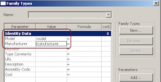
Select the Family Types button to identify the parameters to associate with the look up table. For this example use Model and Manufacturer. In order for this to work correctly some data has to be placed in Value column. The words model and manufacturer will work, the letter X or any other characters will work as well, just don't leave them blank.
 Next a look up table needs to be created. I start with an Excel file that will be converted to a TXT file. Save this file with the same exact name as the family. Only the file extension should be different.
Leave cell A1 blank. Revit reconizes this as a heading for Family type which will start below it. Placing any data here will cause things not to work. Fill out the rest of the cells as indicated below.

 Then change it's exrension in Windows Explorer to ".txt".
  Test this by loading the dishwasher family into a new project.


Column A defines the family Types that can be created.
Column B defines the Model number assigned to that type.
Column C defines the Manufacturer assigned to that type.
The column headers for Model and Manufacturer are a combination of the parameter name to be controlled and a code for the parameter type. The codes are listed below.
- Angle ##ANGLE##DEGREES
- Area ##AREA##SQUARE_FEET
- Currency ##CURRENCY##
- Integer ##OTHER##
- Length ##LENGTH##FEET
- Material ##OTHER##
- Number ##OTHER##
- Slope ##SLOPE##SLOPE_DEGREES
- Text ##OTHER##
- Volume ##VOLUME##CUBIC_FEET
- *Yes/No ##OTHER##
##OTHER##
*When using a Yes/No parameter the Yes=1 and No=0.
When done, save this Excel file with a CSV file type.
Bookcase Family Example
In this example a bookcase family is required that a user can define the HxWxD. The number of shelves should be determined by the height, there should also be a control for the thickness of the material and the option to have doors on the bottom 3 shelves.
To gain the type of control needed, the shelves will have to be nested into the bookcase family. Nesting means the shelves will be an independent family that will be loaded into the bookcase family.
Build the Shelf Family
1. Begin with the Generic Model.rft template.
2. Unpin the 2 references planes in the template and uncheck the Defines Origin check box.
3. Add 4 reference planes to define the length and width of the shelf in the reference view. Set the Right and Back reference planes to Define Origin and Pin them in place.
4. Name the new planes (Front, Back, Left, Right) and set the Is Reference parameter accordingly.
5. Use the Extrusion tool on the Home tab to create a form for the shelf, locking it to the 4 defining planes.

6. Use the dimension tool to dimension the Width and depth of the shelf form.
7. Select the width dimension and pick the Label: drop down on the Options Bar, and then select .

8. The Parameter Properties dialog appears. Fill it out as indicated below. Do the same for the Shelf Depth dimension.

9. Switch to the Front view and create a reference plane to define the top of shelf. Name the reference plane, set its reference to Top and lock the top surface of the shelf form to the plane.
10. Set the shelf’s thickness to ½”. Create a parameter for Shelf Thickness as was done with width and depth.
11. Save this family as A-Fn Bookcase-Shelf.rfa
Build the Bookcase Shell
1. Begin with the Generic Model.rft template.
2. Unpin the 2 references planes in the template and uncheck the Defines Origin check box.
3. Add 4 reference planes to define the length and width of the shelf in the reference view. Set the Right and Back reference planes to Define Origin and Pin them in place.
4. Name the new planes (Front, Back, Left, Right) and set the Is Reference parameter accordingly.
5. Add 3 more reference planes to define the thickness of the back and sides of the bookcase.
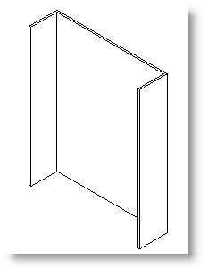
6. Use the Extrusion and trace the footprint of the bookcase sides and back. Lock the faces of the extrusion to the reference planes.

7. Switch to the Front view and create a reference plane to define the top of bookcase. Name the reference plane, set its reference to Top and lock the top surface of the shelf form to the plane.
8. Create parameters for Bookshelf Height, Bookshelf Width, Bookshelf Depth, and Bookshelf Thickness the same way parameters were added to the shelf family.
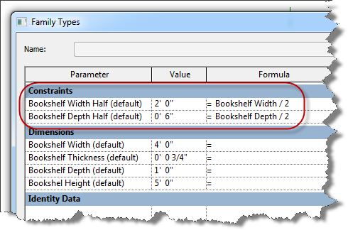
9. Add “half” parameters for the bookcase width and depth. These will be used to keep the center planes in the center.

10. Click the family types button to open its dialog.

11. Group the “half” parameters under constraints and insert the formulas below to ensure they are always half of their parent lengths.
12. This is a good time to flex the family by trying different dimensions in the parameters and checking that the geometry follows suit.
Add the Bottom Bookcase Shelf
The intent here is to add one shelf near the bottom of the shell and array it to the top of the shell. We can then create a parameter to determine the number of shelves in the array. That parameter can be driven by an equation that adds more shelves the taller the bookcase gets.
1. Begin loading the shelf family into the bookcase family and place it off to the side in the reference level view of the bookcase family.
2. Use the Align tool to lock the sides of the shelf to the inside planes of the bookcase shell and the front plane.
3. Select the shelf to access its properties. Here we want to create links between the parameters in the shelf to new parameters in the bookcase to control the shelf’s width, depth and thickness.

5. Do the same for Shelf Width and Shelf Depth.
6. In the Family Type dialog we can now create formulas to keep the shelves the correct size as the case changes. Create the formulas shown in the image below.

Creating a Swappable Shelf
To add another level functionality (or complexity) we can add a parameter that will allow the user to switch from one type of shelf to another.
1. Open the original shelf family and save it as the second shelf option. The shelf below has extrusions added to the bottom.

3. In the Family Types dialog create a new Type parameter named “Swappable Shelf”. Make its discipline Common, its Type of Parameter


5. Select the original shelf in the bookcase family now. In the Properties dialog, look for the Label parameter and change it to “Swappable Shelf”.

6. In the Family Types dialog Create 2 shelf types, Shelf Type 1 and Shelf Type 2. Associate the swappable shelf parameter with the appropriate type.

7. Flex the family. Change the family type and verify that the shelf changes.
Array the Shelf
1. Switch to the front view. And move the shelf up 3”. Add a reference plane to the underside of the shelf. Dimension this plane from the reference level and create a parameter named “Bookshelf Toe-Kick”.

2. Use the Array tool with Group and Associate on and Move To set to “Last”. The array should go from the top of the placed shelf to the top of bookcase reference plane.

3. Select the group and associate line with the current number in the array. On the Options bar select

4. Make it an instance parameter and group it under Constraints.

5. In the Family Types dialog add the equation below to place a shelf at about one shelf per linear foot.

6. Flex the family by changing the height of the bookcase, verifying that the number of shelves changes. Also flex the width, depth, and shelf type.
7. If the shelves lean out of plumb, use the Align tool to lock the upper most shelf in place.
Control the Thickness
For this family the user can input the thickness of the bookshelf, this will in turn drive the thickness of the shelves. Let’s create a formula that allows the user to input any thickness they want, however, if the thickness is less than ½” Revit should use ½” anyway. Conversely if the user specifies any thickness greater than 1”, Revit will use 1” only. If the user specifies any thickness in-between, Revit should consider this a fair value and use it directly.
This requires creating an Actual Thickness parameter and a couple of nested IF statements.
1. Create a new instance parameter and name it Bookshelf Thickness Actual. Group it under Constraints.
2. Apply the following equation to the new parameter.
There are essentially two parts to this nested IF statement.
If (Bookshelf Thickness < 0' 0 1/2", 0' 0 1/2",
This first part states that if the Bookshelf thickness is less than ½” use ½” for the Actual thickness. If it is not, refer to the rest of the statement.
if (Bookshelf Thickness > 0' 1", 0' 1", Bookshelf Thickness))
The last part states that if the Bookshelf thickness is greater than 1” use 1”. If it is not, use the Bookshelf thickness.
3. To finish apply the Actual thickness parameter to the constraining dimension instead of the nominal one.
if(BCS Thickness < 0' 0 1/2", 0' 0 1/2", if(BCS Thickness > 0' 1 3/4", 0' 1 3/4", BCS Thickness))
Using Model Text to Provide User Feedback
Since the user can specify any thickness they want, even if they are wrong, it may be a good idea to provide feedback to the user if the thickness they provide is out of bounds. Model Text will be used for this.
• Place some Model Text on top off the bookshelf and make the text read "XXX".
• Select the Model Text and pick the little square to the right of the Text Parameter in Properties.

• Add a parameter and name it "Thick Condition"
• In the Family Type dialog and a formula as shown below.

• This formula will test to see if the parameters of Bookcase Thickness and Bookcase Thickness Actual are equal. If so the user supplied good data and the model text should read "GOOD". If they are not equal the users supplied bad data and the model text should read "BAD".
Lastly, we only want the model text to display if the condition is "BAD". To do this, create another parameter Called Thick Condition Visible as shown below.

In the Type Parameters dialog, add this formula to the Thick Condition Visible parameter.
Not (Bookcase Thickness = Bookcase Thickness Actual)
This formula returns a true when model text is in a "BAD" condition. When this yes/no parameter is true, it is visible.
The opposite is when the model text is in a "GOOD" condition, the yes/no parameter is false and the Model text will not display.
Important: You must load this family into a project for this to work. The Good and the BAD are visible in the family, but Only Bad is visible once loaded into a project.
Saturday, April 2, 2011
Revit Line Based Families
For this example we are creating a line type that has text in it. To do this, we will create two families, an annotation familiy and a line based familiy. The annotation familiy is nested into the line family. It's easier than it sounds, just follow the steps below.


Create an Annotation Familiy
- Start a new Annotation Symbol familiy using the Generic Annotation template. This template contains two reference planes and some text that is color red. Delete the red text or it will show up in our familiy latter.
- Use the Label tool on the Home tab of the ribbon to add a label right at the intersection of the two reference planes.
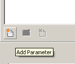
- The Edit Label Properties dialog pops up. Use the Add Parameter button to create a paramter for the line text.
- Fill in the Paramters Properties dialog as indicated below.
- Use the green arrow icon to move the new parameter to the right side of the Edit Label Properties dialog.
- Click the Family Types button on the ribbon and supply a value for the line label. In this case I used the letter 'X'.
- Save this file.


Create a Line Based Detail Componet Familiy
- Start a new family using the Detail Component Line Based template.
- Load the Annotation family we just created into this family.
- Place the annotation familiy just to the right of the left reference plane and let it snap to the horzontal plane.

- Select the question mark. In the Properties dialog pick
Edit Type.
- Check the gray box to the right of the Line Label parameter, add a new parameter and fill out the Parameter Properties dialog as indicated below.

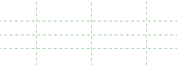
- An array can be used to create multiple labels in the line.
- Don't forget to place an actual line in this family. You may want to create a new subcategory or use one of the the default lines.
- Load this family in a project and test it. Use the the Detail Component tool on the Annotate tab and draw from left to right.
Things to note;
- Types can be created to support different line types like GAS, CW, or C02.
- When using an array short lines will not work. The array used will not allow the lines to get too short. Use a regular detail line to represent short runs.
- This is annotation based, at different scales you will get different results. Build this line type at the scale you plan on using it most of the time, or look into formulas to control the spacing of the labels.
Saturday, March 12, 2011
Revit Families Lesson #2
Reference Planes
Reference planes and reference lines provide the framework for creating forms in Revit.
When creating a new reference plane always draw vertical planes from bottom of screen to top of screen and horizontal planes from left to right. Planes have a positive side and a negative side. Always drawing planes the same way provides predicable results later.
Naming reference planes will help clear confusion once the modeling gets more complex. This is done in the properties of the plane by typing the desired name under Identity Data. A good naming convention will bring clarity to a family especial when revisiting an old family. When adding planes to control solid forms, naming in the format of, <Object> <Location>, (i.e. TableTop, DoorFrameLeft, ControlboxRightside), is an effective way of giving meaning and allowing for ease of use. There may be times when adding a <Use> to the end of a plane’s name is necessary to provide further clarification.

The Is Reference parameter indentifies the location of the plane or determines if that portion of the family can be aligned to or dimensioned to. There are 12 choices for the parameter;
• Left, Center (Left/Right), Right
• Front, center (Front/Back), Back
• Back, Bottom, Top, Center (Elevation)
• Strong Reference, Weak Reference, Not a Reference
To dimension to a plane or snap to it, it must be classified as a strong or weak reference. Strong references have priority over weak references.
The Defines Origin parameter can be applied to three intersecting planes to define an origin point for the family. Consider all three dimensions when specifying the origin point.
Reference Lines
Reference lines have a distinct beginning and end point and are the preferred method for controlling angles. This is because they actually form as two perpendicular planes, meaning that forms can be attached both parallel and perpendicular to the current view.
Adding Parameters
Dimensions can be used to constrain reference planes and lines. Solids and void forms can be locked to these reference planes and lines. If the dimensions are associated with parameters, those parameters can drive the dimensions, planes and forms to create a flexible model that responds to user input as well as logical operators and formulas.
To accomplish this first create the desired dimension using one of Revit’s dimensioning tools.

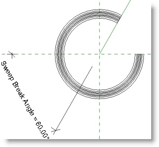
In the image below the angle between a reference plane and a reference line has been dimensioned.

With the dimension selected, pick the tool from the Label drop down on the Options bar.

The Parameter Properties dialog appears. Give the parameter a name. Again, a naming convention is very important. <Object> <Use> works well. This parameter is going to be used to determine the angular size of a break in a sweep form. Group the parameter under Dimensions unless it will be controlled by a formula. In that case group it under Constraints. To give each instance of this sweep individual sweep breaks make this an Instance parameter. To keep them all the same, make this a Type parameter.

When a sweep form is locked to the reference plane and line the new parameter can now control the size of the opening.
To make it simple when working on families, only add annotations and dimensions to the Reference Level, Front Elevation, or the Right Elevation. This helps everyone find parameters that could be in 7 or more views.

Basic Math Operators:
+ Add: 2′ + 0′ 6″ + Length
- Subtract: 1′ 6″ – Width
* Multiply: Length * Width
/ Divide: Length / 2
^ Exponent: x^y, x raised to the y power
log Logarithm
sqrt Square root: sqrt(81)
exp E raised to an x power: exp(2)
abs Absolute Value: abs(-10)
sin Sine: sin(60)
cos Cosine
tan Tangent
asin Arcsine
acos Arccosine
atan Arctangent
Conditional Statements
Conditional statements test for a true or a false condition and then return a value based off the results. The format is this;
IF (, , )
Supported Conditional Operators:
< Less Than
> Greater Than
= Equal to
AND Both statements are true
OR One of the statements is true
NOT Statement is false
a<=b is not supported, but NOT(a>b) can be used to the same effect.
Sample Conditional Statements:
Simple IF Statement
IF (Length < 30′, 2′ 6″, 4′)
Formula That Returns Strings
IF (Height > 30′, “This thing is tall”, “This thing is short”)
Using logical AND
IF (AND (x = 1 , y = 2), 8 , 3 )
Using logical OR
IF (OR (A = 1 , B = 3 ) , 8 , 3 )
Nested IF statements
IF (Length < 35’, 2′ 6″ , IF (Length < 45′, 3′ , IF (Length < 55′, 5′, 8′ ) ) )
IF with Yes/No condition
Length > 40 (The condition and the results are implied)
It is possible to set dimensions equal in Revit by clicking the EQ icon, but it is considered bad practice to use EQ in the Family editor because it can cause the model to become over-constrained easily.
Formulas
Any parameter can have a formula determine its value in the Family Types dialog. Formulas can contain basic math operators and/or conditional statements using integers, decimals, fractional values, and parameter names. Instance and Type parameters can not be used in the same formula.
Subscribe to:
Posts (Atom)