Reference Planes
Reference planes and reference lines provide the framework for creating forms in Revit.
When creating a new reference plane always draw vertical planes from bottom of screen to top of screen and horizontal planes from left to right. Planes have a positive side and a negative side. Always drawing planes the same way provides predicable results later.
Naming reference planes will help clear confusion once the modeling gets more complex. This is done in the properties of the plane by typing the desired name under Identity Data. A good naming convention will bring clarity to a family especial when revisiting an old family. When adding planes to control solid forms, naming in the format of, <Object> <Location>, (i.e. TableTop, DoorFrameLeft, ControlboxRightside), is an effective way of giving meaning and allowing for ease of use. There may be times when adding a <Use> to the end of a plane’s name is necessary to provide further clarification.

The Is Reference parameter indentifies the location of the plane or determines if that portion of the family can be aligned to or dimensioned to. There are 12 choices for the parameter;
• Left, Center (Left/Right), Right
• Front, center (Front/Back), Back
• Back, Bottom, Top, Center (Elevation)
• Strong Reference, Weak Reference, Not a Reference
To dimension to a plane or snap to it, it must be classified as a strong or weak reference. Strong references have priority over weak references.
The Defines Origin parameter can be applied to three intersecting planes to define an origin point for the family. Consider all three dimensions when specifying the origin point.
Reference Lines
Reference lines have a distinct beginning and end point and are the preferred method for controlling angles. This is because they actually form as two perpendicular planes, meaning that forms can be attached both parallel and perpendicular to the current view.
Adding Parameters
Dimensions can be used to constrain reference planes and lines. Solids and void forms can be locked to these reference planes and lines. If the dimensions are associated with parameters, those parameters can drive the dimensions, planes and forms to create a flexible model that responds to user input as well as logical operators and formulas.
To accomplish this first create the desired dimension using one of Revit’s dimensioning tools.

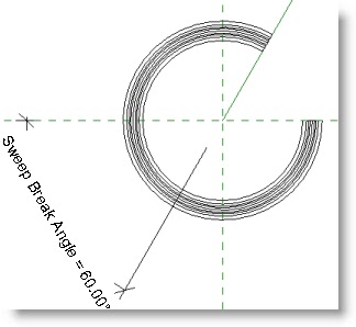
In the image below the angle between a reference plane and a reference line has been dimensioned.

With the dimension selected, pick the tool from the Label drop down on the Options bar.

The Parameter Properties dialog appears. Give the parameter a name. Again, a naming convention is very important. <Object> <Use> works well. This parameter is going to be used to determine the angular size of a break in a sweep form. Group the parameter under Dimensions unless it will be controlled by a formula. In that case group it under Constraints. To give each instance of this sweep individual sweep breaks make this an Instance parameter. To keep them all the same, make this a Type parameter.

When a sweep form is locked to the reference plane and line the new parameter can now control the size of the opening.
To make it simple when working on families, only add annotations and dimensions to the Reference Level, Front Elevation, or the Right Elevation. This helps everyone find parameters that could be in 7 or more views.

Basic Math Operators:
+ Add: 2′ + 0′ 6″ + Length
- Subtract: 1′ 6″ – Width
* Multiply: Length * Width
/ Divide: Length / 2
^ Exponent: x^y, x raised to the y power
log Logarithm
sqrt Square root: sqrt(81)
exp E raised to an x power: exp(2)
abs Absolute Value: abs(-10)
sin Sine: sin(60)
cos Cosine
tan Tangent
asin Arcsine
acos Arccosine
atan Arctangent
Conditional Statements
Conditional statements test for a true or a false condition and then return a value based off the results. The format is this;
IF (, , )
Supported Conditional Operators:
< Less Than
> Greater Than
= Equal to
AND Both statements are true
OR One of the statements is true
NOT Statement is false
a<=b is not supported, but NOT(a>b) can be used to the same effect.
Sample Conditional Statements:
Simple IF Statement
IF (Length < 30′, 2′ 6″, 4′)
Formula That Returns Strings
IF (Height > 30′, “This thing is tall”, “This thing is short”)
Using logical AND
IF (AND (x = 1 , y = 2), 8 , 3 )
Using logical OR
IF (OR (A = 1 , B = 3 ) , 8 , 3 )
Nested IF statements
IF (Length < 35’, 2′ 6″ , IF (Length < 45′, 3′ , IF (Length < 55′, 5′, 8′ ) ) )
IF with Yes/No condition
Length > 40 (The condition and the results are implied)
It is possible to set dimensions equal in Revit by clicking the EQ icon, but it is considered bad practice to use EQ in the Family editor because it can cause the model to become over-constrained easily.
Formulas
Any parameter can have a formula determine its value in the Family Types dialog. Formulas can contain basic math operators and/or conditional statements using integers, decimals, fractional values, and parameter names. Instance and Type parameters can not be used in the same formula.
Enjoy!
ReplyDelete